Inversions of Four Bar Linkage
The term "inversion of mechanism" refers to the practice of fixing one link at a time in a kinematic chain to get different mechanisms. In the four bar linkage mechanism, it is expected that the number of inversions will equal the total number of links in the kinematic chain.
Inversion is done to obtain different motions in a four bar chain mechanism. It should be noted that while the inversion of four bar chain does not affect the relative motions between the various links, it can have a significant impact on their absolute motions (from the fixed link).
Several inversions are commonly used today which are discussed below.
Crank and Lever Mechanism
Figure 2 depicts a portion of the mechanism of a crank and lever mechanism (also known as a beam engine) consisting of four links.

Fig 4: Beam Engine
In this mechanism, the lever oscillates about a fixed centre D when the crank rotates about a fixed centre A. The end E of the lever CDE is connected to a piston rod that reciprocates as a result of the rotation of the crank.
The beam engine mechanism is designed to convert rotary motion to reciprocating motion as shown below. This can be commonly found in oil pumps, water pumps, punching machines, and sawing.

Double Crank Mechanism
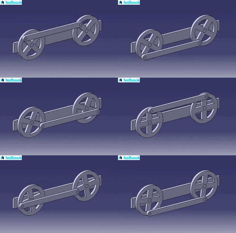
Figure 5 depicts the coupling rod mechanism of a locomotive, also known as a double crank mechanism, which consists of four links.

Fig 5: Coupling Rod Mechanism of Locomotive
In this mechanism, the links AD and BC are of equal length and serve as cranks. They are connected to their respective wheels as shown in figure 5. The link AB is fixed maintaining a constant distance between the centres and the link CD acts as a coupling rod.
The purpose of this mechanism is to transmit rotary motion from one wheel to the other as shown below, and it is commonly used in passenger trains, freight trains, and shunting.

Double Lever Mechanism
A double crank or lever mechanism also referred to as Watt’s indicator mechanism consists of four links as shown in figure 6.

Fig 6: Watt’s Indicator Mechanism
Fixed links at A, link AC, link CE, and link BFD are the four links. It should be noted that since BF and FD do not move relative to one another, they form a single link. CE and BFD form levers. The displacement of link BFD is related to the pressure on the plunger in the indicator cylinder.
The mechanism was originally invented to be used in steam engines but later was used in the rear wheel suspension system of several race cars.
Single Slider Crank Chain
The standard four bar chain is modified to a single slider crank chain. As shown in figure 7, a single slider crank chain has one sliding pair and three turning pairs made up of links 1 and 2, links 2 and 3, and links 3 and 4.
The fixed frame of the engine is represented by link 1. The crank, connecting rod, and cross-head are all represented by links 2, 3, and 4, respectively. The cross-head reciprocates through the guides as the crank turns, which causes the piston to reciprocate in the cylinder.
Here, the rotary motion is changed into reciprocating motion or vice versa using a single slider crank mechanism as shown below. This is commonly found in reciprocating engines, shaping, and slotting machines.

Fig 7: Single Slider Crank Chain
The inversions of the four bar linkage infer that the inversions are possible in any mechanism with four links. There are a few inversions of the slider crank mechanism.
Pendulum pump or Bull engine
The inversion pendulum pump is obtained by fixing the cylinder or link 4 which is a sliding pair as shown in figure 8.

Fig 8: Bull Engine or Pendulum Pump
The piston attached to the piston rod (link 1) reciprocates when the crank (link 2) rotates. This is accomplished by the connecting rod (link 3) oscillating about a pivot pin from the fixed link 4 at A.
The mechanism of the bull engine is used in old water borewells and hand pumps.
Oscillating cylinder engine
To change reciprocating motion into rotary motion, oscillating cylinder engine mechanisms are arranged as in figure 9.

Fig 9: Oscillating Cylinder Engine
Link 3 or the connecting rod in this mechanism is fixed. The piston connected to the piston rod (link 1) reciprocates as the crank (link 2) rotates, and the cylinder (link 4) oscillates about a pin pivoted to the fixed link at A.
This mechanism was primarily used in ships but now it is employed only for toys.
Gnome engine or Rotary IC engine
Aviation industry has employed rotary internal combustion engines. Gas turbines, however, are now used in their place. According to figure 10, the gnome engine has seven cylinders arranged in a single plane, all of which revolve around a fixed centre D.

Fig 10: Gnome Engine
The crank (link 2) is fixed and the piston (link 3) reciprocates inside the cylinders forming link 1 as the connecting rod (link 4) rotates. The rotary IC engine has found its existence in go-karts, snowmobiles, jet skis, chainsaws, racing cars, motorcycles, and power units.
Crank and Slotted Lever Quick Return Motion Mechanism
The crank and slotted lever mechanism is primarily used in rotary internal combustion engines, shaping machines, and slotting machines.

Fig 11: Crank and Slotted Lever Mechanism
According to Figure 11, the turning pair link 3 is fixed. At the fixed centre C, the driving crank CB rotates with a constant rate of angular velocity. The slotted bar AP oscillates about the pivot point A as a result of a sliding block attached to the crank pin at O sliding along the slotted bar.
The clockwise rotation of the crank from position C \(B_1\) to C \(B_2\) (or through an angle \(\beta\)) initiates the forward or cutting stroke. The clockwise rotation of the crank from position C \(B_2\) to C \(B_1\) (or through angle \(\alpha\)) initiates the return stroke.
The mechanism is generally used in cutting, shaping, and slotting machines.
Whitworth Quick return motion mechanism
The Whitworth mechanism is primarily employed by shaping and slotting machines. As seen in figure 12, the link CD (link 2) forming the turning pair is fixed in this mechanism.

Fig 12: Whitworth Mechanism
A constant angular velocity is used to rotate the driving crank CA (link 3). The slotted bar PA (link 1), which oscillates at a pivot point D, is moved by the slider (link 4) attached to the crank pin at point A. The cutting tool fixed to the ram at R is carried by the connecting rod PR.
The mechanism is generally used in high-velocity impact pressing and shaping machines.
Double Slider Crank Chain
The term "double slider crank chain" refers to a kinematic chain that has two turning pairs and two sliding pairs. Generally, the inversion of this four bar linkage mechanism is explained by its inversion as discussed below.
Elliptical Trammel
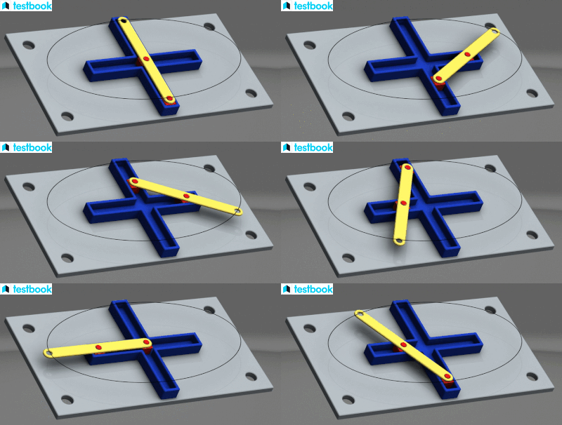
As shown in figure 13, this inversion is achieved by fixing the slotted plate (link 4). Links 1 and 3, known as sliders, combine with link 4 to form sliding pairs.

Fig 13: Elliptical Trammel
The elliptical trammels are utilised to draw ellipses as shown below. They are also used to change tools automatically in CNCs.

Scotch Yoke Mechanism
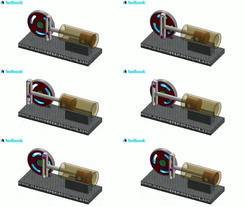
The scotch yoke inversion is achieved by fixing either link 1 or link 3 of the four bar linkage. Referring to figure 14, Link 1 is fixed and link 4 (which represents a frame) reciprocates when link 2 (which represents a crank) rotates around centre B.

Fig 14: Scotch Yoke Mechanism
This mechanism is used in converting the rotary motion to reciprocating motion as seen in practical applications below. It is utilised in many internal combustion engines, including the Bourke engine, as well as numerous hot air engines and steam engines, as well as control valve actuators in high-pressure oil and gas pipelines.

Oldham’s Coupling
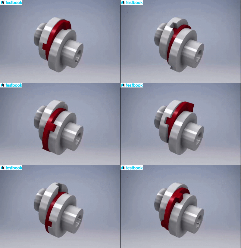
The Oldham’s coupling has a small gap that separates the axes of two parallel shafts. The shafts are joined together so that they rotate at the same speed when one shaft rotates as shown in figure 15.

Fig 15: Oldham’s Coupling
Oldham’s coupling has a widely known application in the transmission system of vehicles and connects two parallel non-coaxial shafts to transmit power. An illustration of its working is shown below.
